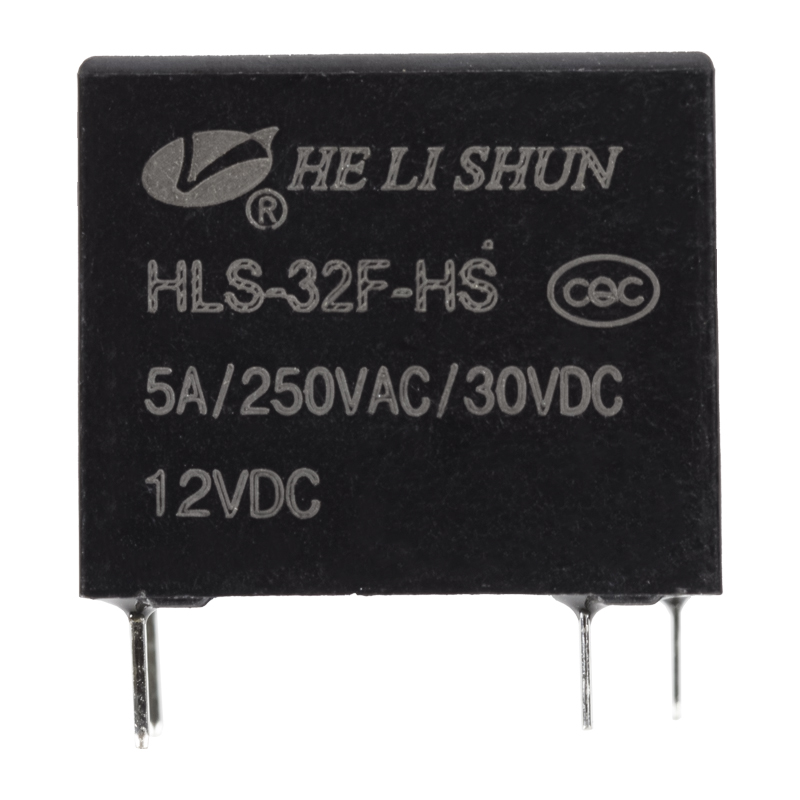
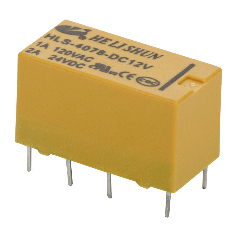
In order to use the relay correctly, please understand the characteristics of the selected relay, confirm whether it is consistent with the use conditions and environmental conditions of the relay, and at the same time, you must master the coil usage method, contact method and environmental conditions of the relay in actual use.
1. Correct selection
To make good use of the relay, it is very important to select the correct type. First, you must have a thorough understanding of the nature, characteristics and use requirements of the controlled object, and consider it carefully. Master and analyze the principles, uses, technical parameters, structural characteristics, specifications and models of the selected relays. On this basis, the relay should be correctly selected according to the actual situation and specific conditions of the project.

2. Understanding of the docking point
The dynamic and static contacts that are disconnected when the relay coil is not energized are called "normally open contacts", otherwise, they are called "normally closed contacts". A moving contact is normally closed with one static contact and normally open with SPDT 5PIN 10A power relay PCB PIN HLS-32F another static contact, and they are called "transfer contacts". In the same relay, there can be one or several pairs of normally open contacts or normally closed contacts (both can also be provided at the same time), and can also have a group or array of changeover contacts.
3. Methods to eliminate contact sparks
Since the on-off current of the relay contacts is small, there will be no arc between the contacts, but "spark discharge" will occur. This is due to the presence of inductance in the contact circuit, and overvoltage will appear on the inductance when it is disconnected, which is different from the power supply voltage. It is added to the contact gap together, so that the contact gap just separated a little distance breaks down and discharges. Due to the limitation of energy, only spark discharge will be generated. The alternating conversion of energy in the capacitance and inductance between the contacts makes the spark discharge appear and disappear and become a high-frequency signal. Furthermore, the spark discharge will also cause damage to the contacts. , which will reduce the service life, so it must be eliminated. There are two practical spark suppression circuits. one. The basic principle of action is to make the energy in the inductor not pass through the contact but pass through rc; two. It is dissipated at the load r.l via the diode v during disconnection. Just choose one in the app. However, it should be noted that the rc parameter should be properly selected, and the parameters are mainly determined by experiments. Usually, the capacitance c can be selected according to the load current 1a/1 microfarad. When using a diode, its positive and negative polarities should be connected correctly.
4. The method of increasing the contact load
In use, if the load capacity of the contacts cannot meet the requirements of use, the method of connecting several pairs of contacts in parallel can be used to solve the problem. However, it should be adjusted before use to make the synchronization of the contacts meet the requirements, otherwise it will be counterproductive. The best way is to use intermediate relays or contactors to expand the load capacity of the contacts.
5. Solutions when the return coefficient does not meet the requirements
The so-called return coefficient kf is a parameter that reflects the degree of cooperation between the suction characteristic and the reaction force characteristic, that is, the difference between the action value and the release value of the relay. Relays for different purposes often require different return coefficients. When the return coefficient of the relay cannot meet the use requirements, a circuit can be used to improve the return coefficient.
6. Improvement of the pull-in release time that does not meet the requirements
When the pull-in and release time of the relay cannot meet the requirements of use, the time constant of the relay coil loop can be changed to solve it.
When it is necessary to accelerate the pull-in, a resistor rf is connected in series in the relay coil loop, and the power supply voltage is appropriately increased to ensure that the pull-in current of the coil remains unchanged, which can achieve the purpose of accelerating the pull-in.


 English
 中文简体
中文简体


